Lignacite Block range
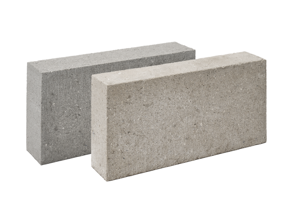
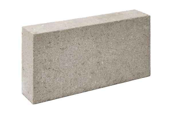
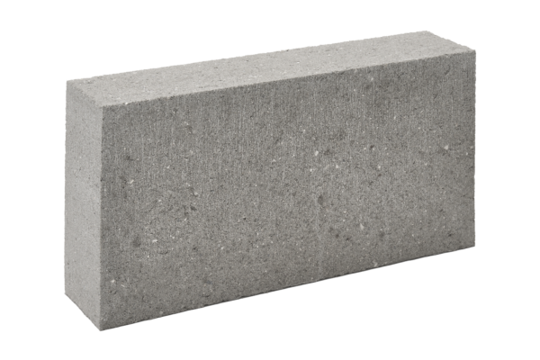
Lignacite concrete blocks are fine textured and available with a paint grade or fair face finish. Manufactured to BS EN 771-3, Lignacite blocks are robust and durable with a technical performance that makes them well-suited to most applications. The blocks’ unique mix design (consisting of cement, fine aggregates and recycled graded-wood particles) accounts for their outstanding technical performance.
The 140mm width version (known as Lignacite SP) has a specially formulated mix that optimises the block density to produce a solid block with a unit weight of less than 20kg. There is a slight colour difference between Lignacite SP and 100mm Lignacite blocks.
Datasheet View our EPDs

Block Benefits
Durable and Robust
Suitable for use in academic, commercial and leisure buildings where durable and impact-resistant walls are needed.
Maintenance-free
Walls built with Lignacite Medium Density blocks will require little or no maintenance throughout their service life.
A1 Fire Rated
These non-combustible blocks make no contribution to fire, earning them a Class A1 rating.
Excellent Sound Insulation
The relatively high mass and low porosity of Lignacite blocks results in outstanding acoustic performance. Walls built using 140mm Lignacite SP blocks can provide sound insulation in excess of 50dB (Rw).
Air Tightness
Lignacite blocks have very low air permeability, especially when painted.
Choose Your Block Variant
Paint Grade Concrete Blocks
Strengths(N/mm2)
3.6
7.3
10.4
Overview
Lignacite Paint Grade are fine-textured concrete blocks that are ideal for walls requiring direct decoration. They are tough, durable and suitable for all types of buildings.
Fair Face Concrete Block
Strengths(N/mm2)
3.6
7.3
10.4
Overview
Lignacite Fair Face are medium density concrete blocks with a fine-textured surface. They are robust, durable and suitable for use in all building types including academic, commercial and leisure projects.
Concrete Block Applications
Lignacite Fair Faced and Paint Grade concrete blocks are suitable for use in commercial, industrial and leisure projects. They can be used in the following locations:
1 of 4
Product Resources
Take a look at our handy downloadable guides, designed to help you get the best from our concrete blocks.
1 of 4
Specification & Application
Block Standards
Lignacite concrete blocks are BSI Kitemarked and certified to BS EN 771-3. They are also Category 1 masonry units manufactured under a BSI certified Quality Management System, which is BS EN 9001 compliant.
Block Appearance
Lignacite concrete blocks are medium grey in colour with a fine textured surface. Blocks are manufactured from natural occurring aggregates, so some colour variation between blocks will be discernible. It is recommended that a sample panel is constructed on site to establish a benchmark for the standard of workmanship and to assess colour variation.
Block Application
For walls that are to be directly decorated, Paint Grade concrete blocks should be specified.
For walls built fair, Fair Face concrete blocks should be specified.
Walls of 210-215mm thickness are recommended to be constructed using two leaves of 100mm Lignacite blocks laid back-to-back and suitably tied. This construction is known as a collar-jointed wall.
Typical locations include:
- The inner leaves of external cavity walls
- Internal walls, including fire break walls
- Separating walls
Block Specification
| Face Size | 440mm x 215mm |
|---|---|
| Thickness | 100mm, 140mm |
| Mean Unit Strength | 3.6/mm², 7.3N/mm², 10.4N/mm² |
| Configuration | Group 1, solid blocks |
| Dimensional Tolerances | Category D1 |
| Net Dry Density | 100mm blocks - 1570 kg/m³.140mm SP blocks - 1450 kg/m³. |
| Thermal Conductivity | 100mm blocks - 0.90 W/mK at 3% moisture content (internal use).140mm SP blocks - 0.79W/mK at 3% moisture content (internal use). |
| Airtightness (m³/hr/m²)No finish | 100mm solid blocks: 3.0.140mm SP solid blocks: 2.8. |
| Airtightness (m³ /hr/m²)Paint one side | 100mm solid blocks: 0.50.140mm SP solid blocks: 0.25. |
| Reaction to Fire | Class A1 |
| Moisture Movement | <0.7mm/m |
| Light Reflectance Value (LRV) for Fair Face blocks | 31% |
| Durability Against Freezing/Thawing | Frost resistance in accordance with PD 6697, Table 15. |
Weights & Pack Sizes
All weights are approximate and subject to normal variations in raw materials.
Table 1 – Concrete Block Weights and Pack Sizes
| Size mm nominal (mm) (L x W x H) | Unit weight (kg) | Laid weight inc. mortar (kg/m²) | No. of blocks per pack |
|---|---|---|---|
| Solid 440 x 100 x 215 | 14.9 | 159 | 72 |
| Solid SP 440 x 140 x 215 | 19.2 | 206 | 48 |
(1) Weights are based on 3% moisture content by weight.
(2) Pack sizes may vary depending on the plant (Brandon or Nazeing) producing and delivering the blocks. For the most up-to-date information, please contact our Sales Team via brandonsales@lignacite.co.uk or nazeingsales@lignacite.co.uk. Alternatively, call our Head Office on 01842 810678.
Fire Resistance
Lignacite concrete blocks are rated as Class A1 in accordance with BS EN 13501-1:2007+A1:2009. A1 materials are completely non-combustible and make no contribution to fire.
The fire resistance periods of Lignacite loadbearing and non-loadbearing walls are shown in Table 2, derived from the National Annex to BS EN 1996-1-2. This is applicable to all strengths of Lignacite.
The fire resistance of loadbearing walls is influenced by the proportion of the load on a wall, which is annotated in the National Annex as a ≤1.0 or a ≤0.6. The fire values presented are based on the worst loading case (≤1.0) and can therefore be safely used for all loading conditions.
The thicknesses shown are for masonry alone, excluding finishes. For the fire resistance of walls with finishes, refer to the Lignacite Design Guide – Fire Resistance.
Table 2 – Fire Resistance
| Block type (No finish) | Non-loadbearing wall (criteria E1) | Loadbearing wall (criteria RE1) |
|---|---|---|
| 100mm solid | 2 hours | 2 hours |
| 140mm solid SP | 4 hours | 3 hours |
(1) Solid blocks are Group 1 units as defined in BS EN 1996-1-1.
Sound Insulation
Due to its relatively high mass and low porosity, Lignacite concrete blockwork provides excellent levels of sound insulation between buildings and adjoining rooms. The Weighted Sound Reduction Index (Rw) values of various Lignacite wall constructions are shown in Table 3.
Table 3 – Sound Reduction Values
Weighted Sound Reduction Index: Rw, (dB):
| No finish | Paint finish | |
|---|---|---|
| 100mm solid | 46 | 47 |
| 140mm SP solid | 49 | 50 |
| 215mm solid (100mm blocks laid flat) | 55 | 56 |
| 200-215mm Collar-Jointed Wall | 51 | 51 |
(1) Sound insulation values are based on technical assessments and tests to BS EN ISO 140-3.
(2) Paint finish is based on emulsion paint and applied to both wall faces.
(3) 215mm walls built using 100mm blocks laid flat cannot be regarding as a fair face wall. However, the construction will be suitable where the appearance of the wall is not important, or if the wall is to have applied finishes.
(4) A Collar-Jointed Wall comprises 2 leaves of 100mm solid blocks laid back-to-back and tied together.
When a higher level of sound insulation is required, Lignacite concrete blockwork can be used in conjunction with a number of acoustic lining treatments, installed on one or both sides of the wall. Blockwork of 100mm and 140mm thickness has been tested and resulted in specifications that are capable of achieving reductions of more than 60 Rw (dB).
Sound Absorption
Lignacite Fair face concrete blocks have sound absorption characteristics considerably better than established data for common masonry materials. Tests on 100mm blocks have confirmed a Weighted sound absorption coefficient (αw) of 0.45 which corresponds to a Class D rating.
This level of sound absorption can make an important contribution towards reducing long reverberation times and echoes whilst improving speech intelligibility. Educational buildings, sports halls and theatres are examples of buildings where sound absorption is likely to be a key design consideration.
Table 4 – Lignacite Wall with Acoustic Linings
| Block Type | Acoustic Lining Specification | Weighted Sound Reduction Index Rw (dB) |
|---|---|---|
| 100mm Lignacite Solid - Lining to one face | 50mm C stud built with 20mm gap from wall, 50mm Isover APR Insulation between studs, 12.5mm Soundbloc plasterboard. | 60 |
| 140mm Lignacite SP - Lining to one face | Isowave 23 system fixed to one wall face. | 56 |
| 140mm Lignacite SP - Lining to both faces | Isowave 23 system fixed to both wall faces. | 65 |
| 140mm Lignacite SP - Lining to one face | 50mm C stud build with 20mm gap from wall, 50mm Isover APR Insulation between studs, 12.5mm Soundblock plasterboard. | 65 |
| 215mm Lignacite - Lining to one face (100mm blocks laid flat) | 50mm C stud build with 20mm gap from wall, 50mm Isover APR Insulation between studs, 12.5mm Soundblock plasterboard. | 66 |
(1) The Isowave system is supplied Isomass Ltd. www.isomass.co.uk
(2) The acoustic lining should be adequately sealed at all exposed edges.
Thermal Properties
The thermal resistance values (m² K/W) for Lignacite blocks are shown in Table 5. The values are calculated by dividing the block thickness by its thermal conductivity (W/mK).
Table 5 – Thermal Resistance Values
| Thermal Resistance (m² K/W): 3% m/c | |
|---|---|
| 100mm solid | 0.111 |
| 140mm SP solid | 0.177 |
(1) 3% moisture content (m/c) should be used for protected locations, such as the inner leaf of external cavity walls.
Presented in the tables are the U-values for a range of wall constructions based on 100mm Lignacite blocks with full and partial cavity insulation. The outer leaf is facing brick, but a rendered block outer leaf will usually achieve at least the same U-value. The U-values assume no surfaces finishes, other than paint.
Full Cavity Fill and 100mm Lignacite blocks
| Cavity fill type | No Finish U-values (W/m² K) |
|---|---|
| 100mm DriTherm Cavity Slab 32 Ultimate | 0.28 |
| 125mm DriTherm Cavity Slab 32 Ultimate | 0.23 |
| 150mm DriTherm Cavity Slab 32 Ultimate | 0.20 |
| 100mm Isover CWS 32 | 0.28 |
| 125mm Isover CWS 32 | 0.23 |
| 150mm Isover CWS 32 | 0.20 |
| 90mm Kingspan Kooltherm K106 (plus a 10mm cavity) | 0.19 |
| 115mm Kingspan Kooltherm K106 (plus a 10mm cavity) | 0.15 |
| 140mm Kingspan Kooltherm K106 (plus a 10mm cavity) | 0.13 |
| 90mm Eurowall + (plus a 10mm cavity) | 0.21 |
| 115mm Eurowall + (plus a 10mm cavity) | 0.17 |
| 140mm Eurowall + (plus a 10mm cavity) | 0.14 |
| 100mm Xtratherm Cavity Therm | 0.20 |
| 125mm Xtratherm Cavity Therm | 0.16 |
| 150mm Xtratherm Cavity Therm | 0.14 |
Partial Cavity Fill and 100mm Lignacite blocks
| Cavity fill type | No Finish U-values (W/m² K) |
|---|---|
| 60mm Celotex CW4000 | 0.26 |
| 75mm Celotex CW4000 | 0.22 |
| 100mm Celotex CW4000 | 0.18 |
| 60mm Kingspan Kooltherm K108 | 0.24 |
| 75mm Kingspan Kooltherm K108 | 0.20 |
| 100mm Kingspan Kooltherm K108 | 0.16 |
| 60mm Eurowall Cavity | 0.26 |
| 75mm Eurowall Cavity | 0.22 |
| 100mm Eurowall Cavity | 0.18 |
| 100mm Rockwool Partial Fill | 0.28 |
| 150mm Rockwool Partial Fill | 0.20 |
| 170mm Rockwool Partial Fill | 0.18 |
| 100mm Isover CWS 32 | 0.27 |
| 125mm Isover CWS 32 | 0.22 |
| 150mm Isover CWS 32 | 0.19 |
(1) The U-values shown are based on the use of various proprietary insulation products. Alternative products can be used, provided they can achieve an equivalent thermal resistance (m² K/W).
(2) Wall ties are assumed to be stainless steel with a cross-sectional area of no more than 12.5mm² for structural cavities up to 125mm wide.
(3) The suitability of full fill cavity insulation materials will depend on exposure conditions and should be confirmed by the designer. For partial cavity fill, a 50mm residual should be maintained (always check the manufacturer’s guidance).
Sustainability
Block Environmental Management and Responsible Sourcing
Our manufacturing plants operate to a BSI certified Environmental Management System (EMS), which complies with ISO14001.
Lignacite Ltd also meets the requirements of BES 6001 – Framework Standard for the Responsible Sourcing of Construction Products (Certificate No: BES 580823). This independently awarded Responsible Sourcing Certification confirms that our products have been made with constituent materials that have been responsibly sourced. This extends to organisational governance, supply chain management and environmental and social aspects, all of which must be addressed in order to ensure the responsible sourcing of construction products. Certification to BES 6001 will allow credits to be gained under environment assessment schemes such as BREEAM.
Block Energy Management
A BSI certified energy management system in accordance with ISO 50001(Certificate No. ENMS 751020) is used to help manage energy use.
Compliance with ISO 50001 is a valuable tool in helping to manage energy use and includes the following outputs.
- A policy for more efficient use of energy
- Fix targets and objectives to meet the policy
- Use data to better understand and make decisions about energy use
- Measure the results
- Review how well the policy works, and
- Continually improve energy management
Block Environmental Performance Declaration (EPD)
Key environmental performance data (in accordance with EN 15804+A2 and ISO 14025/ ISO 1930) can be found in the EPD for Lignacite blocks.
Environmental Data Summary
| Declared unit | 1m² |
|---|---|
| Declared unit mass | 160 kg |
| GWP-fossil, A1-A3 (kgCO2e) | 27.5 |
| GWP-total, A1-A3 (kgCO2e) | 27.9 |
| Secondary material, inputs (%) | 0.0359 |
| Secondary material, outputs (%) | 80 |
| Total energy use, A1-A3 (kWh) | 57.8 |
| Total water use, A1-A3 (m3e) | 1.51E0 |
Source – This data was taken from the EPD for the 7.3N Lignacite block. Click here for all EPDs.
The declared unit is based on 1m² of 100mm thickness blocks.
The Life Cycle Stage (A1-A3) refers to the extraction, processing, transportation and manufacture of materials and products up to the point where they leave the factory gate to be taken to site.
The notation ‘e’ is an abbreviation for tonnes of carbon dioxide equivalent.
Design
Block Structural Design
The design of walls using Lignacite concrete blocks should be in accordance with relevant design standards, including BS 8103: Part 2, BS EN 1996-1-1 and the requirements of the Building Regulations.
Block Movement Control
Vertical movement joints should be considered in accordance with masonry design codes and the recommendations of Published Document PD 6697, at 6.0 – 7.0 metre spacings. In areas of raised stress, such as above and below openings in external walls, the blockwork may need to be reinforced to restrain movement.
Block Service Life
When properly constructed, the durability of walls built using Lignacite products will match that of walls of traditional masonry and will fulfil their intended function for the life of the building in which they have been installed (typically 100 years). The concrete blocks themselves will require no maintenance.
Maintenance for walls will normally include the replacement of sealant in movement joints and at junctions / openings. Repointing for walls that are exposed to the elements may be necessary towards the end of their service life.
Block Wall Ties
Under normal conditions, wall ties should be embedded 50mm into the mortar on each leaf, staggered in alternate courses and spaced in accordance with the following.
Table 6 – Wall Tie Spacings
| Leaf Thickness (mm) | Cavity Width (mm) | Horizontal Spacing (mm) | Vertical Spacing (mm) | Ties per m² |
|---|---|---|---|---|
| Less than 90mm | 50 - 75 | 450 | 450 | 4.9 |
| Over 90mm | 50 - 150 | 900 | 450 | 2.5 |
Block Collar Jointed Walls
When a 200-215mm thick wall is required, it is recommended that a collar-jointed wall is used. This comprises two leaves of 100mm Lignacite blocks laid back-to-back and suitably tied.
Walls can be tied together using metal ties or using masonry reinforcement, e.g., AMR-CJ masonry reinforcement.
Design continued...
Block Mortar
Generally, the mortar type for work above ground level should be designation (iii) / Compressive Class M4. Stronger mixes may be required if blocks are used below ground.
Table 7 – Mortar Mixes
| Mortar Designation (as per BS 5628-3) | Compressive Strength Class (as per BS EN 1996) | Recommended mix proportions of materials by volume |
|---|---|---|
| (iii) | M4 | 1:1:5 to 6 - Cement:Lime:Sand. 1:5 to 6 - Cement:Sand with or without air entrainment. 1:4 to 5 - Masonry Cement:Sand (with non-lime filler). 1:3½:4 - Masonry Cement:Sand (with lime filler). |
| (ii) | M6 | 1:½:4-4½ - Cement:Lime: Sand. 1:3 to 4 - Cement:Sand with or without air entrainment. 1:2½:3½ - Masonry Cement:Sand (with non-lime filler). 1:3 - Masonry Cement:Sand (with lime filler). |
Site Practice
Block Surface Finish Recommendations
Direct Painting
A mist coat followed by at least two coats of emulsion will provide a good finish. The actual coverage will depend on the quality of the paint and how it is applied (e.g., brush, roller or by spray). Always ensure that each coat of paint has fully dried before any further layers are added.
Block Safe Handling
For detailed advice, refer to Lignacite’s Sitework Guide and the Material Safety Data sheet.
- Concrete block packs may be stacked on firm and level surfaces to a maximum height of 2 packs. Consideration of handling equipment’s suitability for site terrain and safety limits should also be given. Hand-operated pallet trucks may not be suitable unless pallets specific for this purpose are used and loads do not exceed the limits of the pallet truck or its operator(s). Care should be taken when opening packs that are wrapped or banded to ensure that items do not fall or otherwise endanger persons handling the blocks or those nearby.
- Handling of concrete blocks should be undertaken in accordance with HSE Construction Sheet No. CIS77 ‘Preventing injury from handling heavy blocks’ (Construction Industry Advisory Committee) and in accordance with the Manual Handling Regulations 1992 (as amended). This concludes that there is a high risk of injury to individuals who repetitively manually handle blocks in excess of 20 kg. Where practical, mechanical handling equipment should be used to transport block packs to the area of work.
- Concrete blocks should not be installed if the temperature is at or below 3°C and falling.
- Concrete blocks should always be laid on a full bed of mortar and vertical joints solidly filled.
- For walls built fair, sample panels are recommended, which should be built prior to commencing concrete block laying. This will serve as a benchmark for defining and specifying the quality of work required.
- It is advisable to view sample panels at a distance of approximately 3m from the wall in good natural light. Fair Face blocks are manufactured from natural occurring aggregates, so some colour variation between blocks will be discernible.